Protocols 9 min read
How IEC 60870-5-104 works: APDU, ASDU, timers and commands
IEC 104 on the wire, from the connection on port 2404 to general interrogation and select-before-operate: I, S and U frames, k and w, t0 to t3, type IDs and causes.
Published:
IEC 60870-5-104 is the IEC standard that carries telemetry and remote control data between a control center and RTUs over TCP/IP. The RTU listens on TCP port 2404, which IANA assigned to the protocol, and the control center opens the connection. Every message on the line is an APDU: a six-byte header that manages the link (the APCI: start byte, length and a four-byte control field), usually followed by an ASDU that carries the data.
IEC 104 keeps most of the application layer of IEC 60870-5-101 and replaces the layers below it with TCP/IP. We compare its data model and event handling with DNP3 in our IEC 104 and DNP3 article. This one looks at the messages on the line, the timers and the typical message flows.
Roles: controlling and controlled station
The standard defines two roles. The controlling station is the control center, a SCADA system or a gateway. The controlled station is the RTU or IED in the field. On the TCP side, the RTU listens on port 2404 as the server and the control center connects as the client.
The APDU: what a message looks like
Every APDU starts with the start byte 0x68. The length byte that follows gives the size of the rest, at most 253 bytes. Then comes the four-byte control field, whose first bits set the frame format:
| Format | What it carries | When it is sent |
|---|---|---|
| I | Numbered data: one ASDU | Measurements, states, commands and interrogations |
| S | Acknowledgment only: the next I-frame number expected | To acknowledge received frames when there is no data to send |
| U | Link control: STARTDT, STOPDT, TESTFR | To start or stop data transfer and to test the link |
I-frames carry two sequence numbers: the send number N(S) and the receive number N(R). Each side counts the frames it sends and puts the number it expects next from the other side in N(R), which acknowledges every frame before it. If a message is lost or arrives out of order, the numbers no longer match, and the connection is closed and set up again.
How a connection starts
- The control center opens a TCP connection to port 2404 on the RTU. The time allowed for this is t0.
- The control center sends STARTDT act and the RTU answers with STARTDT con. Until then only U-frames may cross the line; data transfer starts with this step.
- The control center sends a general interrogation and gets the current value of every point.
- From then on, the RTU sends changed values spontaneously.
- If no message crosses the line for a while, either side sends TESTFR act and the other answers with TESTFR con. If no answer comes, the connection is closed.
k and w: unacknowledged frames
The sender may have at most k unacknowledged I-frames outstanding. At that limit it stops and waits for an acknowledgment. The receiver acknowledges after w I-frames at the latest: in the N(R) field of its own I-frame if it has data to send, or with an S-frame if it does not. The standard recommends that w not exceed two thirds of k.
Timers: t0, t1, t2, t3
| Parameter | Standard default | Meaning |
|---|---|---|
| t0 | 30 seconds | Time allowed to set up the TCP connection |
| t1 | 15 seconds | Time to wait for an acknowledgment of a sent I- or U-frame; then the connection is closed |
| t2 | 10 seconds | Latest time to acknowledge received I-frames when there is no data to send |
| t3 | 20 seconds | Idle time before a test frame is sent |
| k | 12 | Maximum number of unacknowledged I-frames |
| w | 8 | Maximum number of I-frames received before an acknowledgment |
t2 has to be shorter than t1. If it is longer, the sender’s t1 runs out before the acknowledgment arrives and the connection drops. On high-latency links such as satellite or cellular modems, these values can be raised, but the control center and the RTU must be set to match. Check both sides’ documentation before you change them.
ASDU, type IDs and causes of transmission
The ASDU inside an I-frame has these fields:
- Type identification (1 byte): the kind of data, such as a single point, a measured value or a command.
- Variable structure qualifier (1 byte): the number of information objects in the message and whether their addresses are consecutive (the SQ bit).
- Cause of transmission (2 bytes in IEC 104): why the message was sent. The same field holds the negative confirmation (P/N) and test bits and the originator address.
- Common address of ASDU (2 bytes): the station address. One RTU can use several common addresses.
- Information objects: each with a 3-byte information object address (IOA), a value, quality and, where the type has one, a time tag.
Common types:
| Type | Mnemonic | Meaning |
|---|---|---|
| 1 | M_SP_NA_1 | Single point, a two-state value (ON/OFF) |
| 3 | M_DP_NA_1 | Double point, such as a breaker position |
| 13 | M_ME_NC_1 | Measured value, short floating point |
| 30 | M_SP_TB_1 | Single point with a CP56Time2a time tag |
| 31 | M_DP_TB_1 | Double point with a CP56Time2a time tag |
| 36 | M_ME_TF_1 | Measured value, short floating point, with time tag |
| 45 | C_SC_NA_1 | Single command |
| 46 | C_DC_NA_1 | Double command |
| 100 | C_IC_NA_1 | General interrogation |
A double point takes four values: 0 intermediate, 1 OFF, 2 ON, 3 indeterminate. A moving breaker shows as intermediate for a moment. If it stays intermediate or indeterminate, something is wrong. Measured values and states come with quality bits: invalid (IV), not topical (NT), substituted (SB) and blocked (BL) tell you how far to trust the value.
Common causes of transmission:
| Code | Meaning |
|---|---|
| 1 | Periodic |
| 3 | Spontaneous (the value changed) |
| 6 | Activation: a command or interrogation request |
| 7 | Activation confirmation |
| 10 | Activation termination |
| 20 | Response to a general interrogation |
The CP56Time2a time tag
In time-tagged types, each value comes with a seven-byte time tag: milliseconds including seconds, minutes, hours, day of month with day of week, month and a two-digit year. The IV bit in the minutes byte marks the time as invalid, and the SU bit in the hours byte marks summer time.
To sort an event list correctly, this tag is more reliable than the time the message reached the control center. Many RTUs buffer events while the link is down and send them when it returns, so the events arrive late but with their own time. The standard does not say whether the time is local or UTC. If the project does not settle this, events show up shifted by the time zone difference.
The general interrogation flow
When a connection comes up, or whenever it needs to, the control center asks for the current state of all data with a general interrogation:
- The control center sends C_IC_NA_1 to the RTU with cause of transmission 6 (activation).
- The RTU answers with the same type and cause 7 (activation confirmation).
- The RTU sends every point with cause 20.
- The RTU reports the end of the interrogation: C_IC_NA_1 with cause 10 (activation termination).
If the control center sends a general interrogation after every reconnect, the screen gets the current state again. Changes that came and went during the outage arrive only if the RTU buffered them as events.
The command flow: select and execute
Single and double commands carry an S/E bit: 1 means select, 0 means execute. With select-before-operate, the flow is:
- The control center sends the command with S/E = 1 (select) and cause 6.
- The RTU answers with cause 7. If the P/N bit is negative, the selection was rejected.
- The control center sends the same command with S/E = 0 (execute) and cause 6.
- The RTU confirms with cause 7.
- Many RTUs report activation termination with cause 10 when the command is done.
Direct execute skips the first two steps. The result in the field comes separately: if the breaker really opened, the RTU reports the new position in a double point message. The position on the operator’s screen should follow that feedback.
Security
IEC 104 defines no authentication or encryption of its own: anyone listening on the line can read the messages, and anyone with network access can send commands. In practice the basic safeguard is network separation. Keep the RTUs on their own network segment and allow access to port 2404 only from the control center. We cover the security extensions of IEC 62351 in our IEC 104 and DNP3 article.
Common problems in the field
- The connection comes up but no data arrives: STARTDT was not sent or the RTU did not answer it. A capture of the traffic shows only test frames.
- The connection drops at regular intervals: t1 is running out. The link may have high latency, or the two sides’ k, w and timer values do not match.
- Values land on the wrong points: the common address or IOA is defined differently on each side. Some devices let you change the address lengths; standard IEC 104 uses 2 bytes for the common address and 3 for the IOA.
- Event times are shifted: the RTU and the control center do not agree on local time, UTC or summer time.
- The command goes out but the breaker does not move: the selection may have been rejected, or the RTU is in local control. Check the P/N bit in the confirmation.
In YTCC
The IEC 60870-5-104 driver in YTCC works as the controlling station (master). It sends a general interrogation when it connects, a setting that is on by default. The CP56Time2a time sent by the device is stored as the event time, and the message’s arrival time is kept separately; if the time tag is invalid, the arrival time is used. The event list and alarm history are sorted by device time. The intermediate and faulty states of a double point show separately on screen.
For commands, the driver sends single commands. Select-before-operate is enabled per point, and the execute message does not go out until the RTU gives a positive confirmation. YTCC has a core written in Rust. Each driver instance, IEC 104 included, runs in its own operating system process. When communication with a device is lost, one alarm is raised for that device and its signals drop to “no connection” quality.
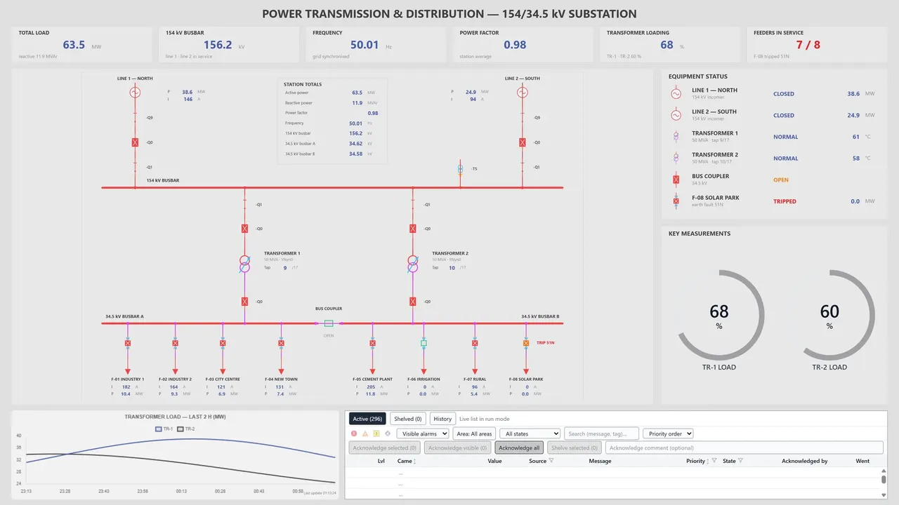
For energy projects, see the Power Transmission and Distribution page. The other protocols YTCC talks to are on the Platform page.